Injection-Molding Mechanical Design
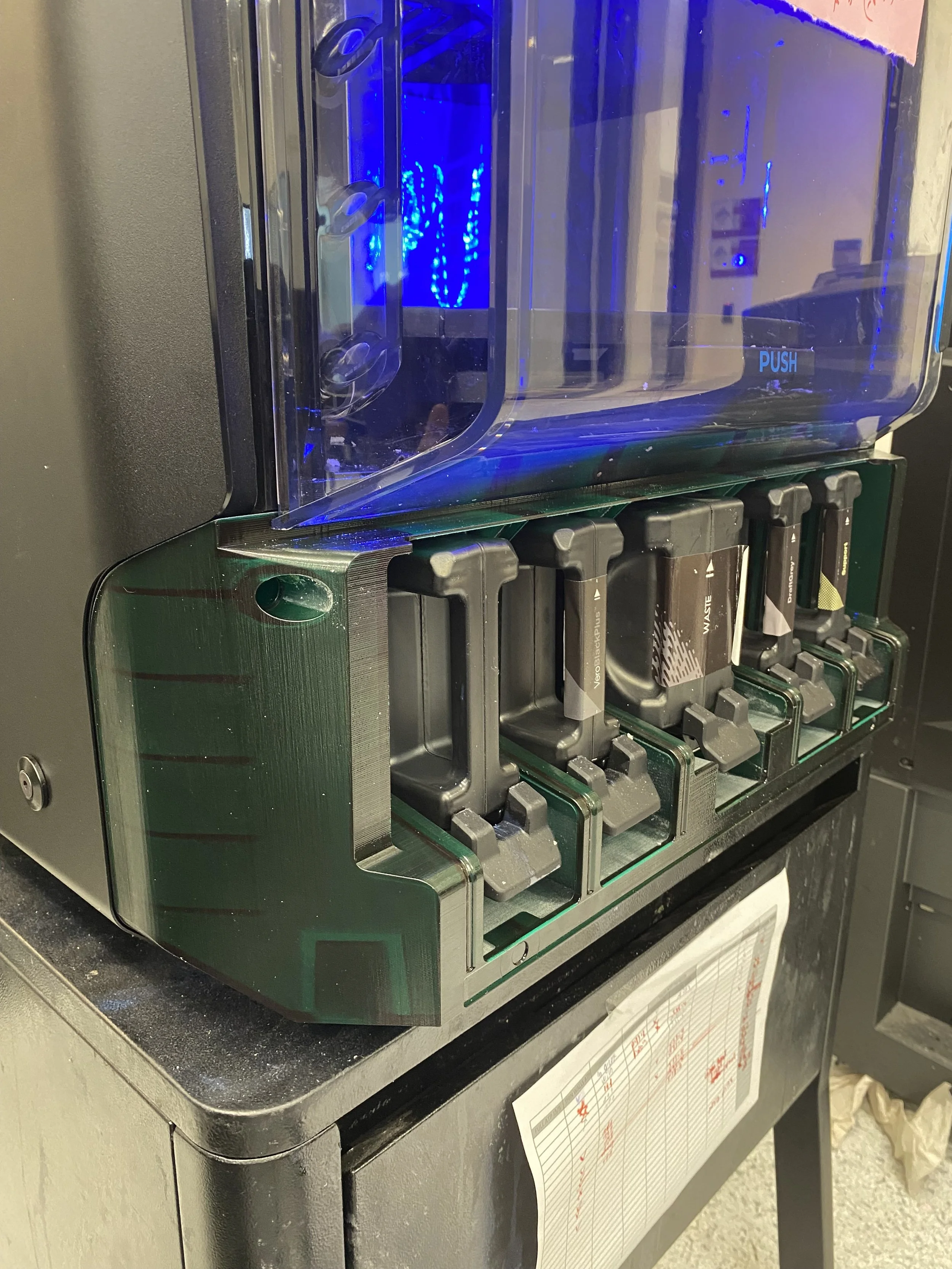
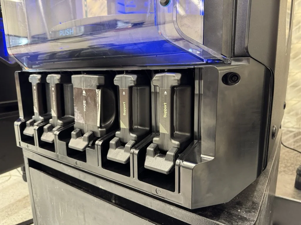
J3 Materials Bay Bezel
CAD | RC Analysis | Asian Manufacturing | Operations
July 2023 - December 2024

Project Scope and Motivation
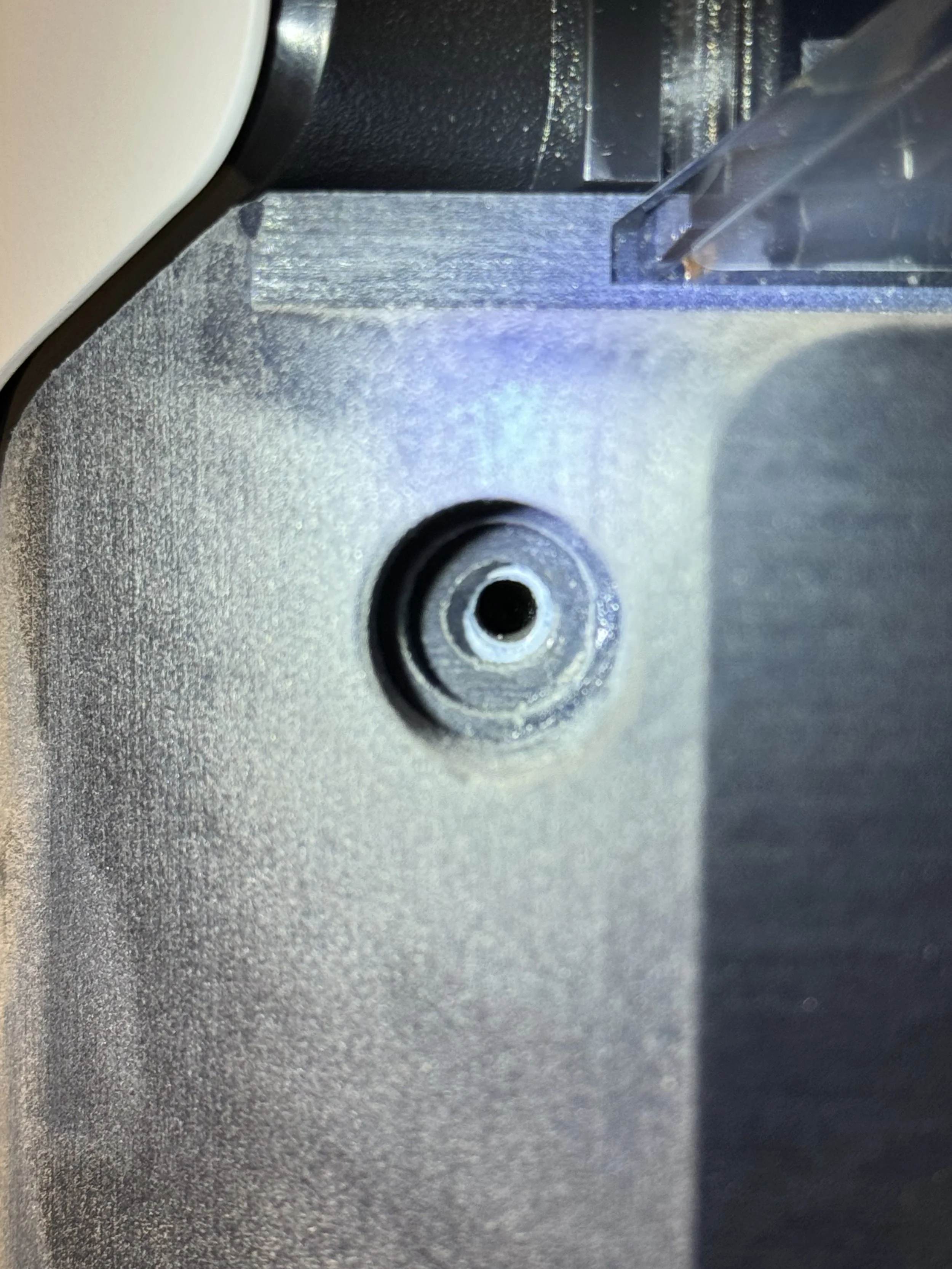
Solve plastic breakage in mounting bosses, affecting 70% of existing printers.
Eliminate post-injection machining required to avoid interference with the printer’s internal components.
Keep machine functionality and appearance unchanged.
Manufacturing cost savings goal: ~$90 per part.
Operational savings goal: ~$150,000 yearly.
ROI: less than 36 months
Research and Root Cause Analysis
My research focused on Design for Manufacturability (DFM) of injection-molded plastics, Mold-Flow analysis and materials science.
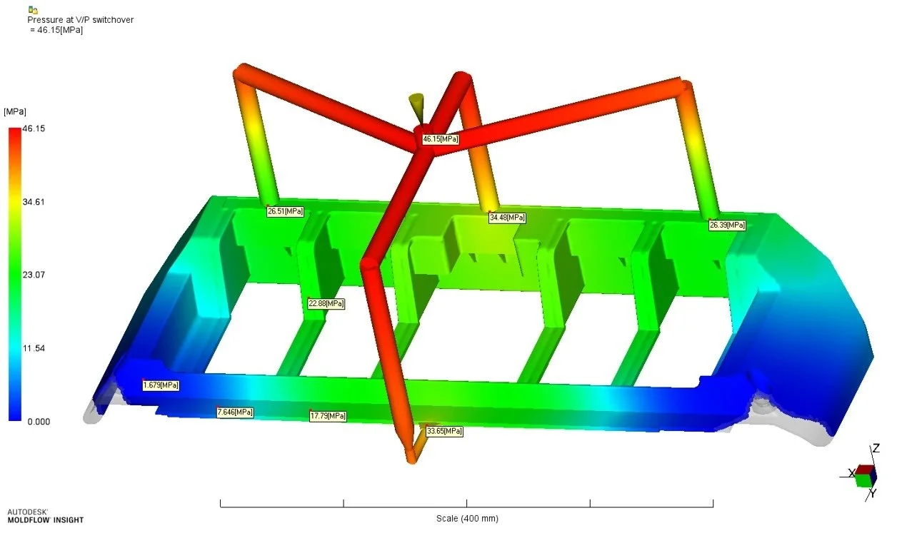
Root Cause Analysis found the failure to be caused by compromised material flow characteristics in the mold, resulting in steep cooling gradient in target areas. This caused stresses cracking and subsequent failure.
Decision: design new part to solve breakage, and eliminate the need for post-injection machining.
Designing for injection molding is a constant balance of geometry and flow behavior.
The smallest design change to a feature sometimes barely visible to the naked eye, can result in a profound change to the flow characteristics of the liquid plastic in the mold, which in turn can have an impact on the part’s post-injection warpage, structural stability, visual appearance, and more
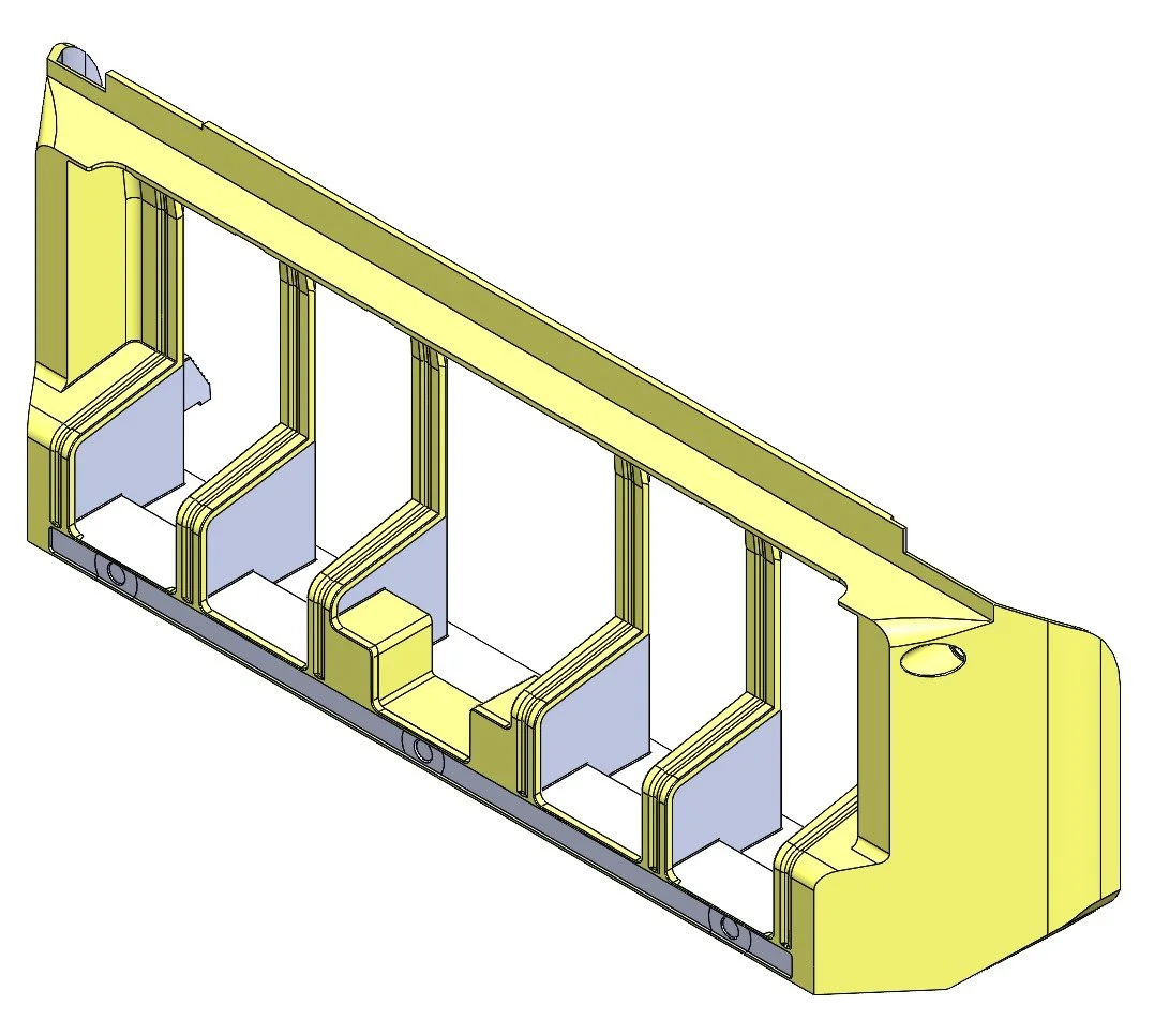
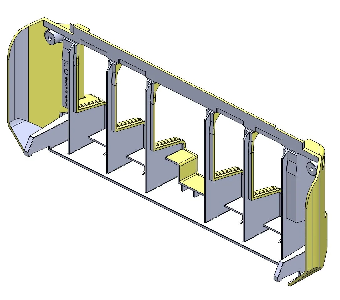
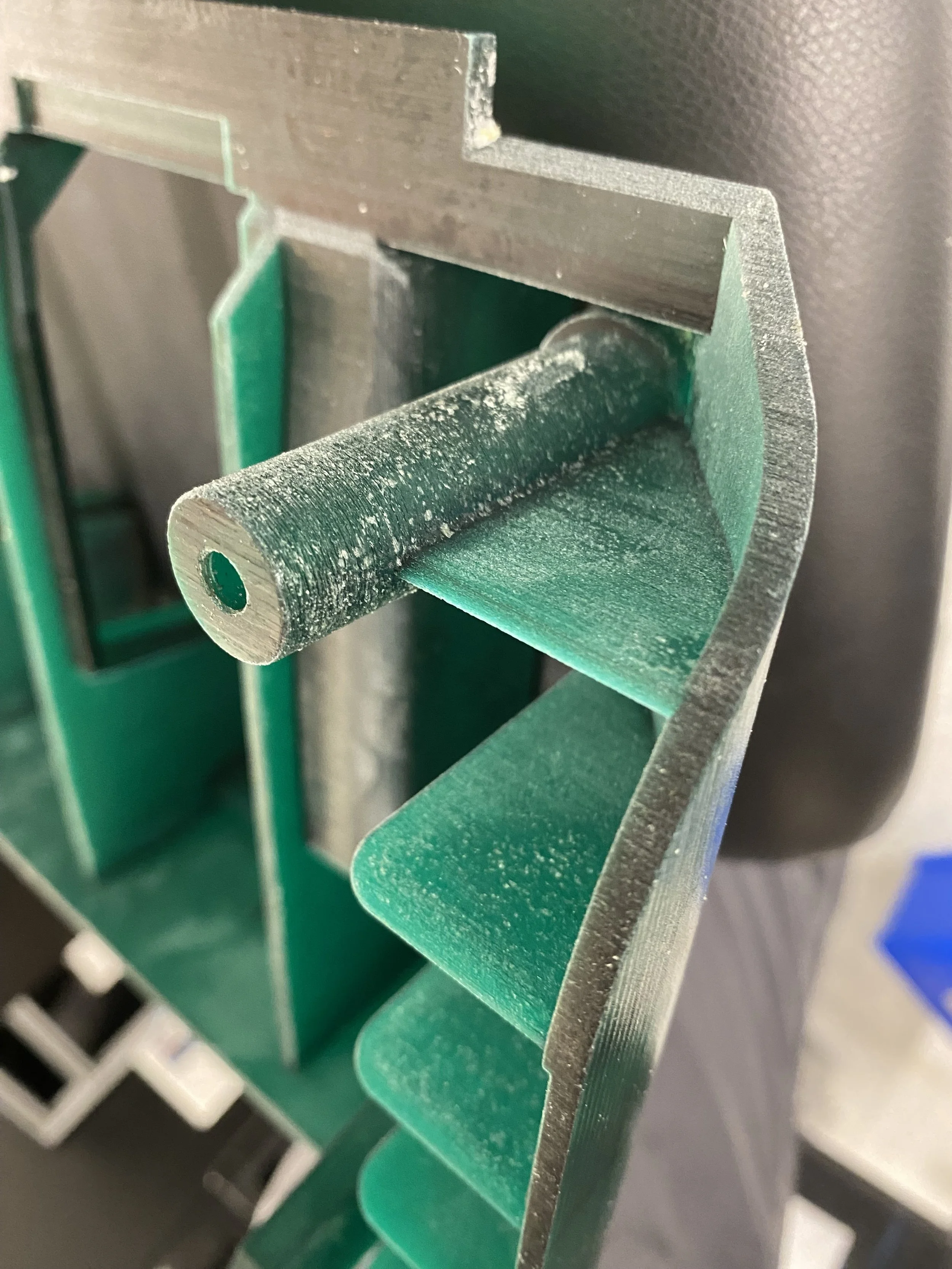
Achieving the desired cosmetic finish relies on careful, meticulous design of the part’s hidden geometry - the internal structures that act as its backbone.
Certain constraints, such as support ribs needed for post-injection stability, can be thick enough to cause “sink marks” on the visible surface.
When constrains cannot be fully mitigated through design, a controlled cosmetic sink mark feature is introduced to meet visual requirements.
Design Process
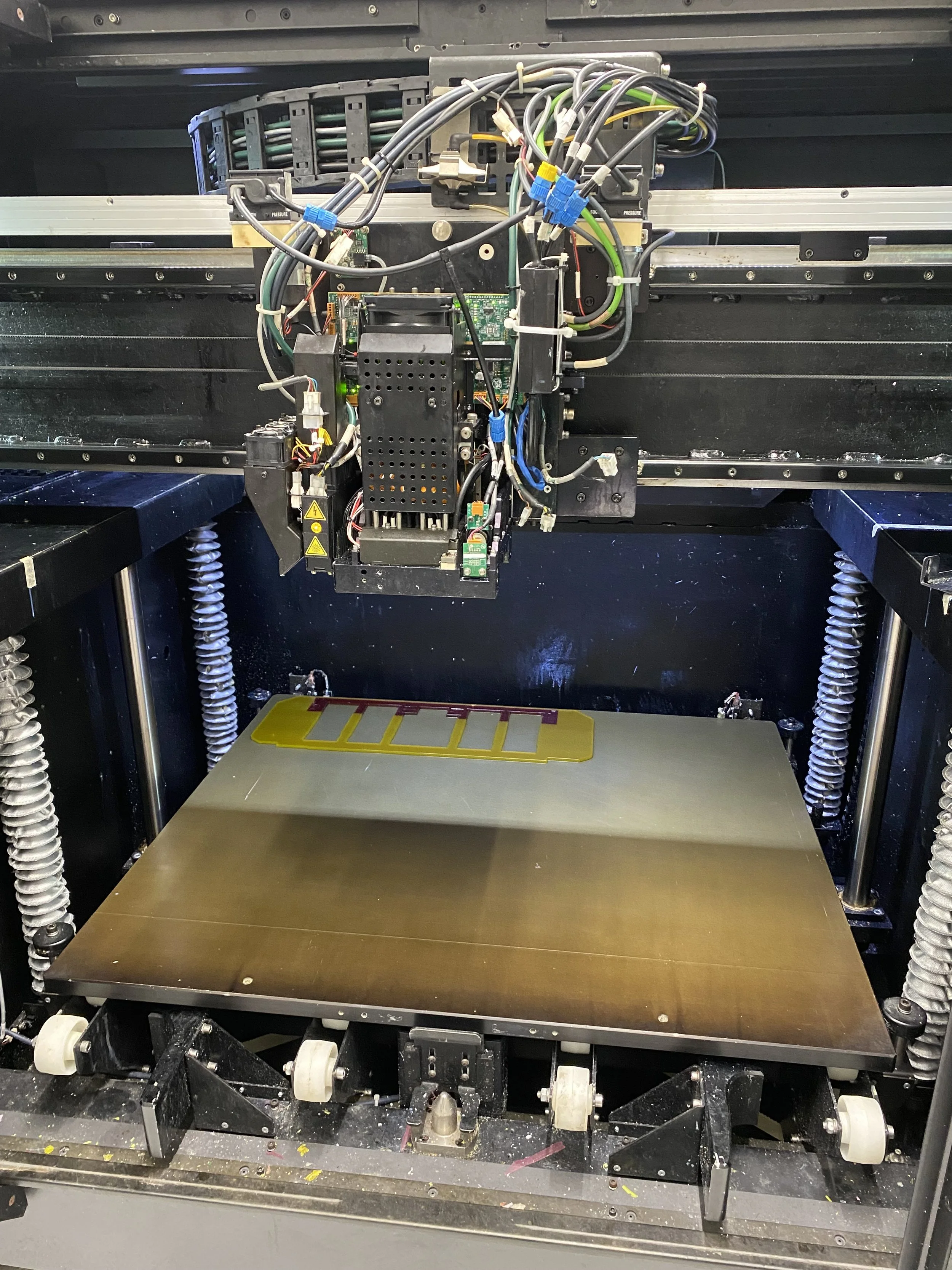
Design Verification and Validation was completed after 5 prototype iterations, printed on an in-house large-scale PolyJet 3D printer.
Testing various solutions to improve flow characteristics in designated areas.
Each design change required running a full Mold Flow simulation, as even the smallest of modifications can dramatically change flow characteristics in the mold.
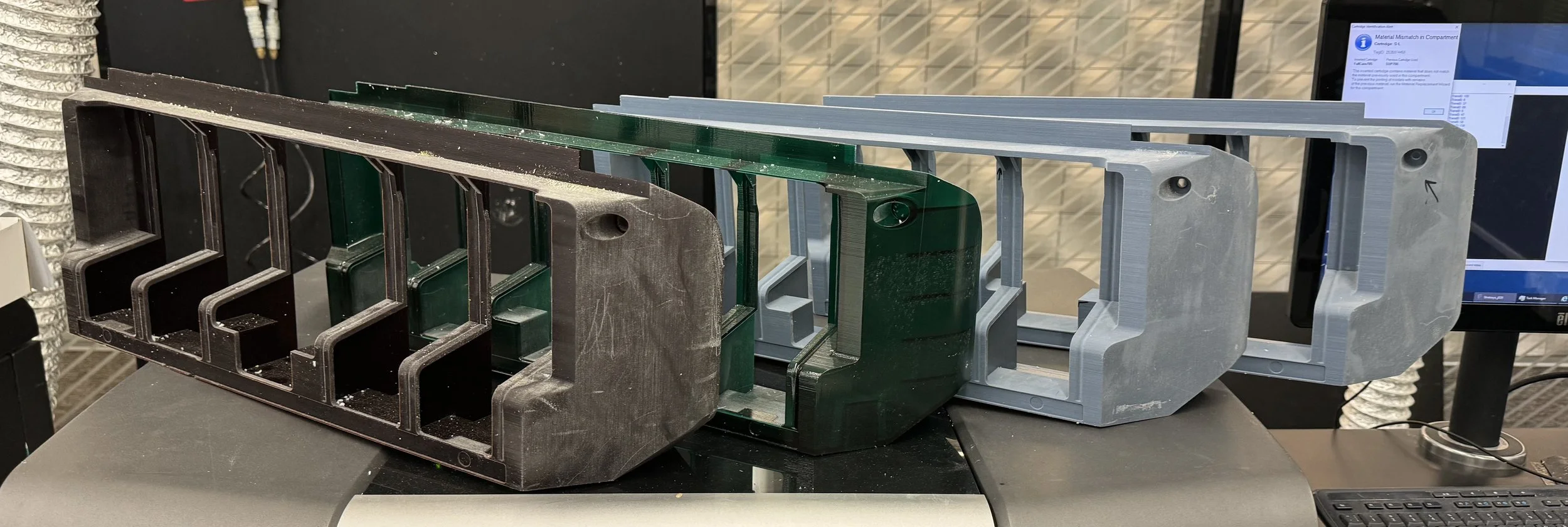
In-house prototype printing allowed for a very quick design change verification process, and saved expenses on prototype-specific injection mold.
Even failed prints did not slow the design process!
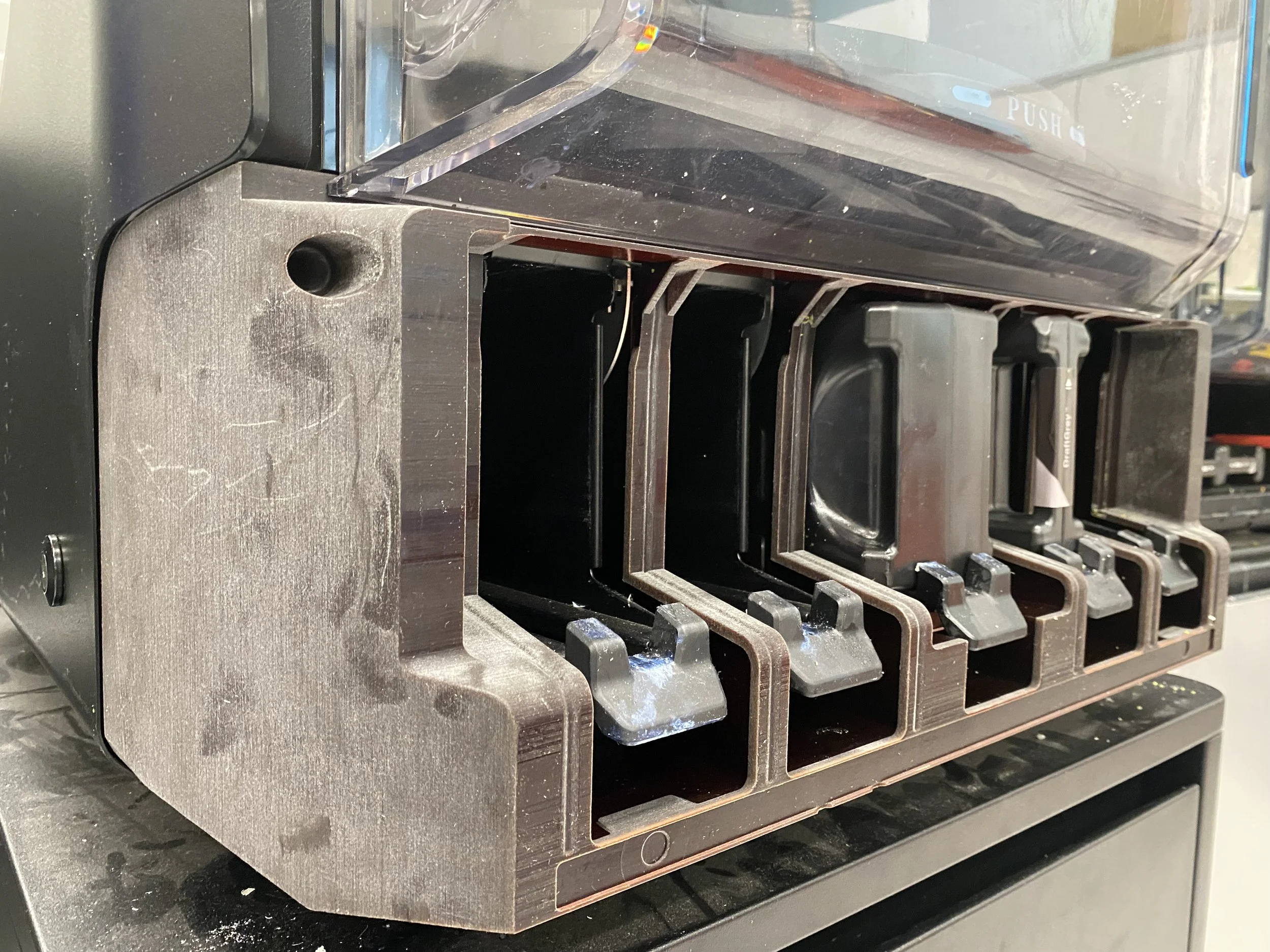
First injection run was successful, achieving dimensional stability and eliminated the failure mechanism.
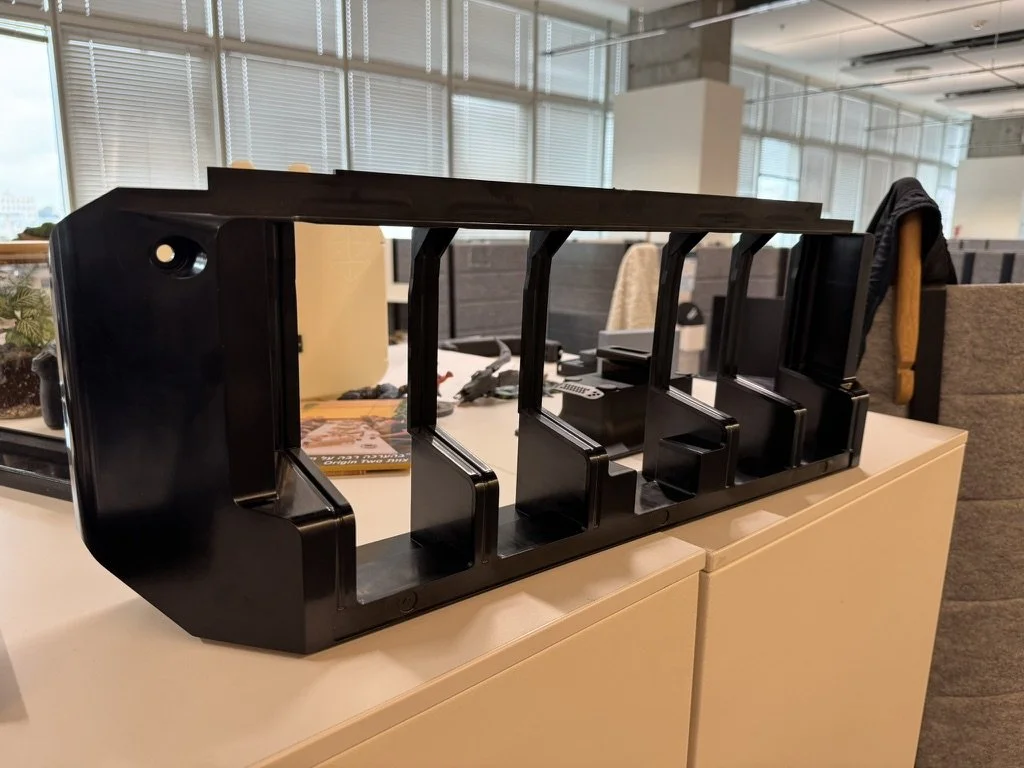
First assembly :)
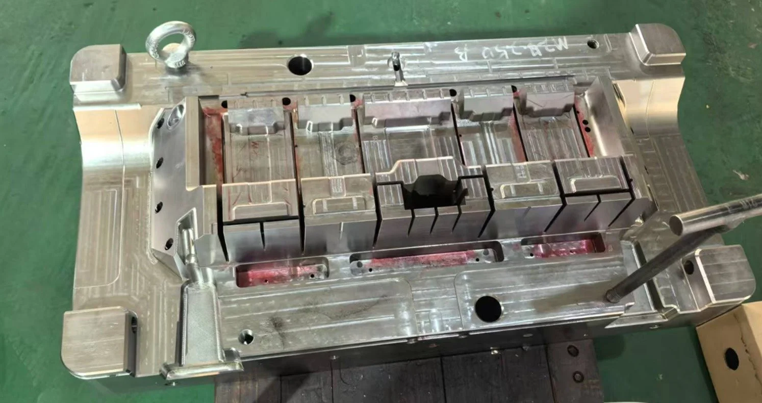
Production
-
Mold manufacturing in China began after four DFM sessions.
Design work carried out alongside Moldflow simulations enabled rapid mold development.
The mold was finalized, polished, and the injection process stabilized after the T2 phase.
-
FAI process included CMM testing, stress and vibrations testing and beta phase.
All tests passed successfully and no revisions were required.
-
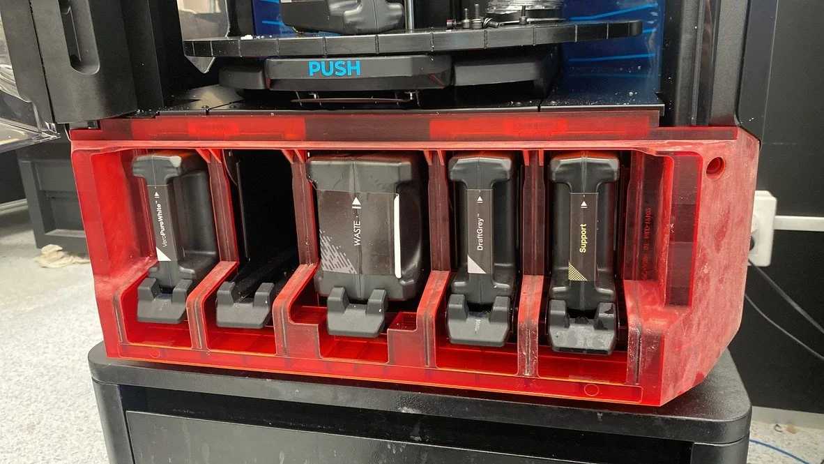
The part was successfully implemented in the printer’s BoM
A service plan to replace failed parts in hundreds of printers globally was created.
The project met its targets, and ROI is projected in 30 months.
-
I received an internal “Excellence Recognition” reward for the project successful outcome.
Following the successful implementation, I’ve created an organization-wide injection-molding seminar for mechanical and product designers, to pass forward the knowledge I’ve gathered.
